How Does Concrete Move Through the Machine?
Concrete moves through four main stages: material preparation, mixing, hopper transfer, and hydraulic delivery. Each stage hands the material to the next, so the sequence is easier to understand as a flow than as a list of unrelated components.
1. Materials enter the mixer
Cement, aggregate, and water enter the drum or forced mixer through the fitted feeding arrangement. Manual or volumetric feeding can serve simple work; controlled aggregate weighing with an aggregate batching machine is more suitable when batch proportions need tighter control. Irregular dosing changes concrete consistency before pumping even begins.
2. The mixer prepares a pumpable batch
The mixer combines the materials until the batch reaches its intended consistency. Mixer volume, blade or drum action, loading sequence, water control, aggregate grading, and mixing time determine when the batch is ready to leave the mixer. Extra water should not be used as a quick answer to difficult pumping because it can change the intended concrete properties.
3. Concrete drops into the hopper
Once mixed, the concrete enters the hopper above the pumping cylinders. A screen keeps oversized material away from the pumping mechanism, and the agitator keeps concrete moving around the cylinder inlets. The hopper is therefore a working buffer, not just a storage box.
4. The pump sends concrete through the line
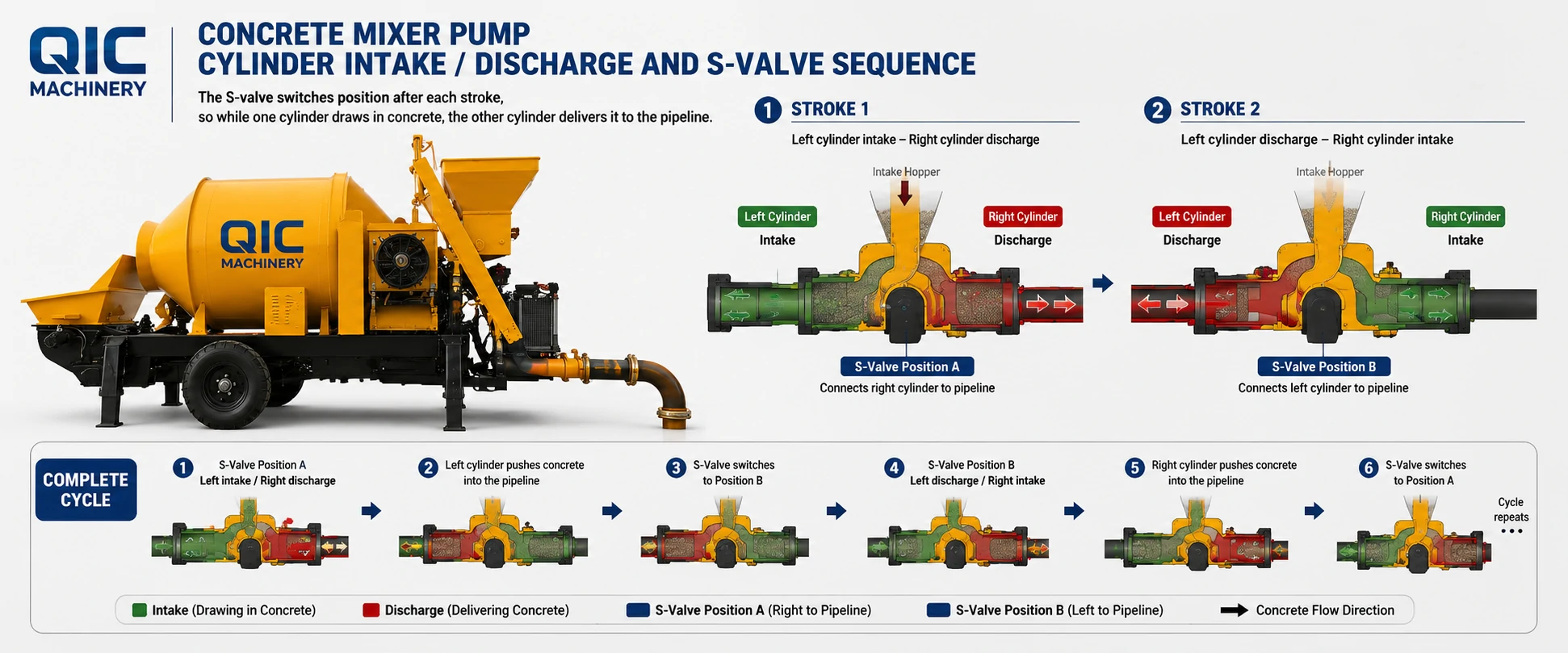
Hydraulic power moves two concrete pistons in alternating strokes. One cylinder fills from the hopper while the other discharges through the S-valve. Concrete then travels through straight pipes, bends, reducers, and the end hose to the placement point.
| Stage | Concrete movement | Main parts involved |
|---|---|---|
| Feed | Cement, aggregate, and water enter the machine | Feeding equipment, water system, mixer inlet |
| Mix | Materials become a uniform, pumpable batch | Drum or forced mixer, drive, blades |
| Transfer | Mixed concrete moves into the pumping inlet | Discharge opening, hopper, screen, agitator |
| Pump and place | Alternating strokes move concrete into the delivery line | Hydraulics, twin cylinders, pistons, S-valve, pipes |
What Happens Inside the Twin Cylinders and S-Valve?
The twin cylinders create alternating suction and discharge strokes, while the S-valve connects the discharging cylinder to the pipe outlet. Together they turn separate piston movements into a near-continuous concrete flow.
During one half of the cycle, the first piston retracts and draws concrete from the hopper into its cylinder. At the same time, the second piston advances and pushes the concrete already inside its cylinder toward the outlet. The S-valve is aligned with that discharging cylinder.
At the end of the stroke, the valve switches sides. The first cylinder now discharges, the second draws in a new charge, and the sequence repeats. Cutting rings and wear plates help seal the switching area; wear there allows internal leakage and weakens material transfer.
Why Does the Hopper Need Constant Concrete?
The hopper must keep both cylinder inlets supplied while the pistons alternate. If its level falls too low, the cylinders can draw air instead of a full charge of concrete, making flow less stable.
The screen and agitator also protect this transfer point. Oversized aggregate can obstruct the inlet, while concrete that sits without movement can segregate around the cylinders. A steady mixer discharge and visible hopper level give the pumping section a consistent material supply.
What Controls Pressure in the Delivery Line?
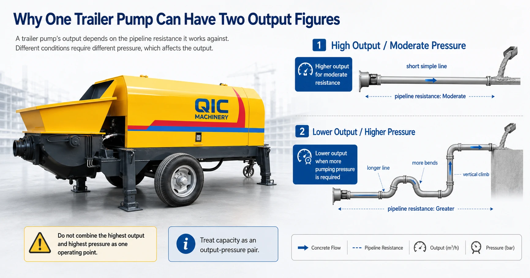
Pipeline resistance rises with vertical height, total length, bends, reducers, end-hose length, concrete consistency, aggregate size, and the condition of the pipe. The hydraulic system must create enough pressure to overcome that combined resistance.
A short, mostly horizontal line is easier to pump than a long vertical line with several elbows. In the harder layout, pressure capacity, concrete pumpability, pipe diameter, secure supports, and sound clamps become more important than the headline cubic metres per hour. Using the wrong pipe class or poorly supporting a bend also creates a safety risk.
Why Can Actual Output Be Lower Than Pump Output?
Actual placement can be lower because the pumping unit is only one stage in the cycle. A loader that falls behind, a longer mixing time, an empty hopper, difficult concrete, or a resistant pipe layout can leave the hydraulic pump waiting or working below its theoretical rate.
This is why nominal pump output should not be read as the guaranteed hourly production of the complete machine. Mixer batch volume, feeding method, hopper continuity, concrete data, horizontal run, vertical rise, and bend count all belong in a practical output estimate.
Do Mixer Type and Power Source Change the Principle?
Drum or forced mixing and diesel or electric power change how the machine is supplied and operated, but they do not change the twin-cylinder and S-valve pumping principle. Both versions still mix, transfer, draw, discharge, and place concrete in the same basic order.
A drum mixer keeps the arrangement compact for standard small-site preparation. If the mix needs more intensive action or controlled dosing, a forced mixer and aggregate batching equipment may be more suitable; feeding height, power demand, cleaning work, and wear points also change.
Diesel drive is useful where industrial electricity is unavailable or unreliable. Electric drive needs the correct voltage, frequency, phase, transformer capacity, cable length, and grounding, but avoids engine fuel and exhaust where the supply is stable.

What Happens Before the First Batch and After the Last?
Before pumping starts, the machine needs firm level ground, a properly supported delivery line, suitable clamps and seals, water, lubrication, trained roles, and the model-specific operating manual. Priming follows the procedure for the supplied machine and pipe layout.
After the final placement, the operator empties the system, stops pumping, releases line pressure by the approved procedure, and cleans the mixer, hopper, cylinders, S-valve area, pipes, bends, and end hose. No clamp, outlet, or washout point should be opened while the delivery line remains pressurized.
Washout cannot wait. Concrete left inside the machine or pipeline can harden in the areas that are hardest to reach before the next start.
How We Use the Work Cycle to Select a Mixer Pump
We start with the complete material and delivery flow, because the mixer, pump, and pipework must work at compatible rates. Your required hourly and shift volume, feeding method, aggregate size, slump range, horizontal pipe length, vertical rise, bends, end-hose length, power supply, access, water supply, and operator plan show where the cycle will face its highest demand.
Our engineers use those details to narrow the mixer type, diesel or electric drive, pumping duty, pipe diameter and quantity, accessories, initial wear parts, and operating material. If budget comparison is the next step, use the concrete mixer pump price guide to separate the machine from pipework, parts, freight, and startup items.
Conclusion: Mixing, Transfer, and Pumping Form One Cycle
A concrete mixer pump works by preparing a batch, feeding an agitated hopper, alternating two pumping cylinders through an S-valve, and carrying concrete through a delivery line. Hopper continuity and pipeline resistance connect the mechanical stages, while depressurizing and cleaning close the cycle safely.
Send us your concrete volume, material data, feeding method, pipeline layout, power supply, access, water, and schedule. We can define the mixer, pumping unit, pipes, accessories, parts, and startup information needed for that operating cycle. Contact us with those details.